brake light Ram 1500 2014 Get to Know Guide
[x] Cancel search | Manufacturer: RAM, Model Year: 2014, Model line: 1500, Model: Ram 1500 2014Pages: 252, PDF Size: 6.74 MB
Page 3 of 252

INTRODUCTION/WELCOME
WELCOME FROM CHRYSLER
GROUP LLC.................. 3
CONTROLS AT A GLANCE
DRIVER COCKPIT ............... 6
INSTRUMENT CLUSTER .......... 8
GETTING STARTED
KEYFOB ................... 10
KEYLESS ENTER-N-GO™ ......... 12
REMOTE START .............. 13
VEHICLE SECURITY ALARM ....... 14
SEATBELT .................. 15
SUPPLEMENTAL RESTRAINT
SYSTEM (SRS) — AIR BAGS ....... 16
CHILD RESTRAINTS ............ 17
HEAD RESTRAINTS ............. 24
FRONT SEATS ................ 25
HEATED/VENTILATED SEATS ....... 27
HEATED STEERING WHEEL ........ 30
TILT STEERING COLUMN ......... 31
OPERATING YOUR VEHICLE
ENGINE BREAK-IN
RECOMMENDATIONS........... 32
TURN SIGNALS/WIPER/WASHER/HIGH
BEAMS LEVER................ 33
HEADLIGHT SWITCH ............ 34
SPEED CONTROL .............. 35
EIGHT-SPEED AUTOMATIC
TRANSMISSION — IF EQUIPPED .... 37
ELECTRONIC RANGE SELECT (ERS)
OPERATION ................. 38
1500 AIR SUSPENSION SYSTEM .... 40
2500-3500 AIR SUSPENSION
SYSTEM .................... 42
MANUAL CLIMATE CONTROLS
WITHOUT TOUCHSCREEN ........ 43
MANUAL CLIMATE CONTROLS
WITH TOUCHSCREEN ........... 44
AUTOMATIC CLIMATE CONTROLS
WITH TOUCHSCREEN ........... 45
PARKSENSE
®FRONT AND REAR
PARK ASSIST ................ 46
PARKVIEW®REAR BACK-UP CAMERA.. 47
POWER SLIDING REAR WINDOW .... 47
POWER SUNROOF ............. 48
WIND BUFFETING ............. 49
ELECTRONICS
YOUR VEHICLE'S SOUND SYSTEM . . . 50
IDENTIFYING YOUR RADIO ........ 52
Uconnect
®ACCESS ............. 53
Uconnect®3.0 ................ 67
Uconnect®5.0 ................ 70 Uconnect
®8.4A ............... 78
Uconnect®8.4AN .............. 96
STEERING WHEEL AUDIO
CONTROLS ................. 115
ELECTRONIC VEHICLE INFORMATION
CENTER (EVIC) .............. 116
PROGRAMMABLE FEATURES ...... 117
UNIVERSAL GARAGE DOOR OPENER
(HomeLink
®) ................ 120
POWER INVERTER ............ 123
POWER OUTLETS ............ 124
OFF-ROAD CAPABILITIES
FOUR WHEEL DRIVE OPERATION . . . 126
UTILITY
TONNEAU COVER............. 129
EASY-OFF TAILGATE ........... 129
PICKUP BOX ................ 130
RAMBOX
®.................. 132
TOWING & PAYLOAD ........... 136
TOW/HAUL MODE ............ 138
INTEGRATED TRAILER BRAKE
MODULE .................. 138
RECREATIONAL TOWING
(BEHIND MOTORHOME, ETC.) ..... 140
1500 3.0L DIESEL
DIESEL ENGINE BREAK-IN
RECOMMENDATIONS........... 145
DIESEL ENGINE STARTING
PROCEDURES ............... 155
DIESEL FUEL FILTER/WATER
SEPARATOR ................ 147
EXHAUST REGENERATION ....... 148
COOL-DOWN IDLE CHART ........ 162
ADDING FUEL — DIESEL ENGINE
ONLY ..................... 163
DIESEL EXHAUST FLUID ........ 164
6.7L CUMMINS® DIESEL
DIESEL ENGINE BREAK-IN
RECOMMENDATIONS........... 155
DIESEL ENGINE STARTING
PROCEDURES ............... 155
DIESEL EXHAUST BRAKE
(ENGINE BRAKING) ........... 157
IDLE-UP FEATURE (AUTOMATIC
TRANSMISSION ONLY) ......... 158
ENGINE MOUNTED FUEL
FILTER/WATER SEPARATOR ....... 158
UNDERBODY MOUNTED FUEL
FILTER/WATER SEPARATOR ....... 160
EXHAUST REGENERATION ....... 161
COOL-DOWN IDLE CHART ........ 162
ADDING FUEL — DIESEL ENGINE
ONLY ..................... 163
DIESEL EXHAUST FLUID ........ 164
TABLE OF CONTENTS
Page 10 of 252

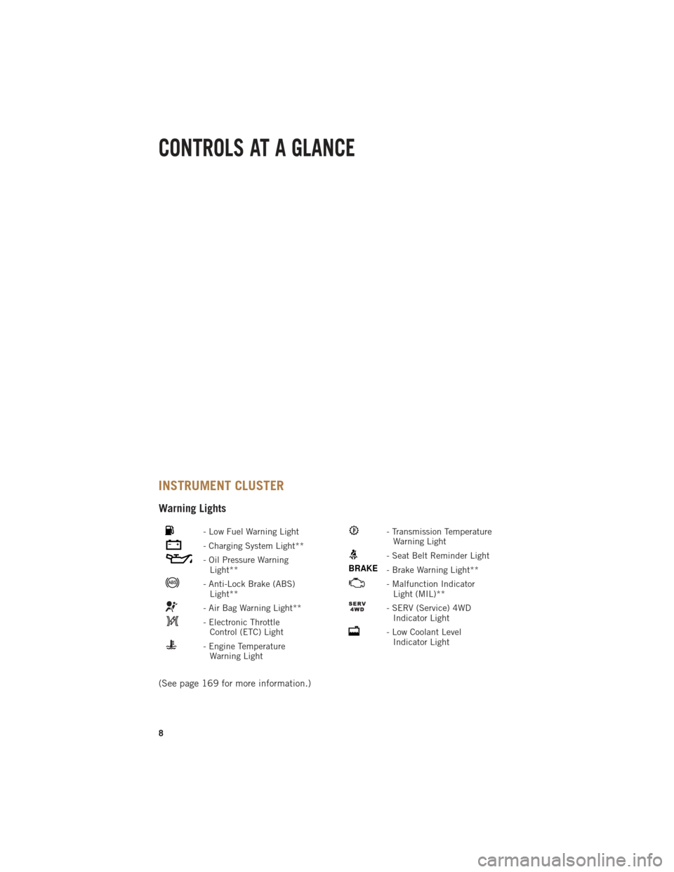
INSTRUMENT CLUSTER
Warning Lights
- Low Fuel Warning Light
- Charging System Light**
- Oil Pressure WarningLight**
- Anti-Lock Brake (ABS)Light**
- Air Bag Warning Light**
- Electronic ThrottleControl (ETC) Light
- Engine TemperatureWarning Light
- Transmission TemperatureWarning Light
- Seat Belt Reminder Light
BRAKE- Brake Warning Light**
- Malfunction IndicatorLight (MIL)**
- SERV (Service) 4WDIndicator Light
- Low Coolant LevelIndicator Light
(See page 169 for more information.)
CONTROLS AT A GLANCE
8
Page 13 of 252

Locking And Unlocking The Doors
•Press and release the UNLOCK button on the RKE transmitter once to unlock the
driver’s door. Press the UNLOCK button twice within five seconds to unlock all doors
and the tailgate and the RamBox
®(if equipped). The turn signal lights will flash to
acknowledge the unlock signal. The illuminated entry system will also turn on.
NOTE:
The EVIC can be setup for driver door first, otherwise this will unlock all doors.
All doors can be programmed to unlock on the first press of the UNLOCK button.
Refer to Programmable Features in this guide.
Panic Alarm
• Press the PANIC button once to turn the panic alarm on.
• Wait approximately three seconds and press the button a second time to turn the panic alarm off.
RKE Air Suspension (Remote Lowering Of Vehicle) — If Equippedx2
• This vehicle is equipped with a feature that can lower the vehicle to a height which
will improve ease of passenger entry/exit and cargo loading/unloading. The feature
is accessed by pressing the air suspension lowering button twice on the key fob.
• When remote key fob lowering is requested the vehicle will send a series of chirps and flashes to alert the customer that the operation has begun and will continue
these alerts until it successfully lowers.
• If the feature is unable to lower the vehicle due to certain conditions not being met, the horn will chirp twice and the vehicle will not lower.
Emergency Key
Should the battery in the vehicle or the Key Fob transmitter go dead, there is an emergency
key located in the Key Fob that can be used for locking and unlocking the doors.
•To remove the emergency key, slide the button on the Key Fob with your thumb and
then pull the key out with your other hand.
WARNING!
• Never leave children alone in a vehicle, or with access to an unlocked vehicle. Allowing children to be in a vehicle unattended is dangerous for a number of
reasons. A child or others could be severely injured or killed. Children should
be warned not to touch the parking brake, brake pedal, or the shift lever. Do not
leave the Key Fob in or near the vehicle, or in a location accessible to children,
and do not leave the ignition of a vehicle equipped with Keyless Enter-N-Go™
in the ACC or ON/RUN mode. A child could start the vehicle, operate power
windows, other controls, or move the vehicle.
• Do not leave children or animals inside parked vehicles in hot weather. Interior
heat build-up may cause them to be severely injured or killed.
GETTING STARTED
11
Page 119 of 252

PROGRAMMABLE FEATURES
Programmable Features
The EVIC can be used to view or change the following settings. Press the UPor
DOWN
button until System Setup displays, then press the RIGHTbutton.
Scroll through the settings using the UP or DOWN buttons. Press the RIGHT
button to change the setting. Press the BACK/LEFTbutton to scroll back to a
previous menu or sub menu.
• Radio Info • Trip Info
• Fuel Economy Info • Tire Pressure
• Cruise Control Info • Vehicle Info
• Digital Vehicle Speed • Stored Warning Messages
• Stop/Start • Turn Menu OFF
• Screen Setup • Trailer Tow
Uconnect® Customer Programmable Features
The Uconnect®system allows you to access Customer Programmable feature settings
such as Display, Clock, Safety/Assistance, Lights, Doors & Locks, Auto-On Comfort &
Remote Start, Engine Off Operation, Compass Settings, Audio, Trailer Brake, Phone/
Bluetooth
®, Suspension and SiriusXM Setup and System Information through soft-keys.
•Press the SETTINGS button (Uconnect®5.0), or press the “Apps” button (Uconnect®
8.4) located near the bottom of the touchscreen, then press the “Settings” button on the
touchscreen to access the Settings screen. When making a selection, scroll up or down
until the preferred setting is highlighted, then press and release the preferred setting
until a check-mark appears next to the setting, showing that setting has been selected.
The following feature settings are available:
• Display • Clock
• Safety/Assistance • Doors & Locks
• Auto-On Comfort & Remote Start • Engine Off Options
• Phone/Bluetooth
®• Audio
• Lights • SiriusXM Setup
• Compass (Uconnect
®5.0) • Trailer Brake
• Suspension • System Information
• Units • Voice
NOTE:
Depending on the vehicles options, feature settings may vary.
ELECTRONICS
117
Page 120 of 252

EVIC Reconfigurable Screen Setup
The following settings allow you to change what information is displayed in the
instrument cluster as well as the location that information is displayed.
Digital Speedometer
• Press and release the UP or DOWN arrow button until the Digital display icon ishighlighted in the EVIC. Press and release the RIGHT arrow button to change the
display between km/h and mph.
Vehicle Info (Customer Information Features)
• Press and release the UP or DOWN button until the Vehicle Info icon is highlightedin the EVIC Display. Press and release the RIGHT or LEFT to scroll through the
following Vehicle Info submenus:• Tire Pressure Monitor System
• Air Suspension — If Equipped
• Coolant Temperature (Diesel Only)
• Transmission Temperature (ATX Only)
• Oil Temperature
• Oil Pressure
• Oil Life
• Fuel Filter Life (Diesel Only)
• Battery Voltage
• Exhaust Brake (Diesel Only)
• Turbo Boost (Diesel Only)
• Gauge Summary
• Coolant Temperature (Diesel Only)
• Transmission Temperature (ATX Only)
• Oil Temperature
• Oil Pressure
• Engine Hours
Trip A
• Press and release the UP or DOWN arrow button until the Trip A icon is highlighted in the EVIC. Press and hold the RIGHT arrow button to reset the Trip A information.
Trip B
• Press and release the UP or DOWN arrow button until the Trip B icon is highlightedin the EVIC. Press and hold the RIGHT arrow button to reset the Trip B information.
ELECTRONICS
118
Page 140 of 252

TOW/HAUL MODE
• When driving in hilly areas, towing a trailer, carrying a heavy load, etc., andfrequent transmission shifting occurs, press the TOW/HAUL switch to select
TOW/HAUL mode. This will improve performance and reduce the potential for
transmission overheating or failure due to excessive shifting. When operating in
TOW/HAUL mode, transmission upshifts are delayed, and the transmission will
automatically downshift (for engine braking) during steady braking maneuvers.
• The “TOW/HAUL Indicator Light” will illuminate in the instrument cluster to
indicate that TOW/HAUL mode has
been activated. Pressing the switch a
second time restores normal operation.
If the TOW/HAUL mode is desired, the
switch must be pressed each time the
engine is started.
INTEGRATED TRAILER BRAKE MODULE
The Integrated Trailer Brake Controller allows you to automatically or manually
activate the Electric Trailer Brakes and Electric Over Hydraulic Trailer Brakes for a
better braking performance when towing a trailer.
NOTE:
The Integrated Trailer Brake Controller is located in the center stack below the
climate controls.
This module will have four different options depending on the type of trailer you want
to tow and can be selected through the 3.5” Electronic Vehicle Information Center
(EVIC) or touchscreen radio.
• Light Electric
• Heavy Electric
• Light EOH (Electric Over Hydraulic)
• Heavy EOH (Electric Over Hydraulic)
UTILITY
138
Page 144 of 252

Shifting Into NEUTRAL (N)
Use the following procedure to prepare your vehicle for recreational towing.
WARNING!
You or others could be injured or killed if you leave the vehicle unattended with the
transfer case in the NEUTRAL (N) position without first fully engaging the parking
brake. The transfer case NEUTRAL (N) position disengages both the front and rear
driveshafts from the powertrain and will allow the vehicle to move, even if the
transmission is in PARK. The parking brake should always be applied when the
driver is not in the vehicle.
CAUTION!
It is necessary to follow these steps to be certain that the transfer case is fully in
NEUTRAL (N) before recreational towing to prevent damage to internal parts.
1. Bring the vehicle to a complete stop, with the engine running. Firmly apply the parking brake.
2. Shift the transmission to NEUTRAL.
3. Press and hold the brake pedal.
4. Depress the clutch pedal on a manual transmission.
5. If the transfer case is in 4WD AUTO (if equipped), press a selector button or rotate the selector switch to shift the transfer case into the 2WD or 4WD LOCK position.
• With manual shift transfer case, shift the transfer case lever into NEUTRAL (N).
• With electronic shift transfer case, press and hold the transfer case NEUTRAL (N) button. Some models have a small, recessed "N" button (at the center of the
transfer case switches) that must be pressed using a ballpoint pen or similar
object. Other models have a rectangular NEUTRAL switch, below the rotary
transfer case control knob. The NEUTRAL (N) indicator light will blink while the
shift is in progress. The light will stop blinking (stay on solid) when the shift to
NEUTRAL (N) is complete. After the shift is completed and the NEUTRAL (N)
light stays on, release the NEUTRAL (N) button.
6. Release the parking brake.
7. Shift the transmission into REVERSE.
8. Release the brake pedal (and clutch pedal on manual transmissions) for five seconds and ensure that there is no vehicle movement.
9. Repeat steps 7 and 8 with automatic transmission in DRIVE or manual transmis- sion in first gear.
10. Shift the transmission to NEUTRAL. Firmly apply the parking brake. Turn OFF the engine. For vehicles with Keyless Enter-N-Go™, press and hold the ENGINE
START/STOP button until the engine shuts off.
UTILITY
142
Page 145 of 252

11. Shift the transmission into PARK or place manual transmission in gear (NOT inNeutral). On 8-speed transmissions the shifter will automatically select PARK
when the engine is turned off.
12. Turn the ignition switch to the OFF position, then cycle the key or the Keyless Enter-N-Go™ button to the RUN position and back to the OFF position.
13. Attach the vehicle to the tow vehicle using a suitable tow bar.
14. Release the parking brake.
NOTE:
With electronic shift transfer case:
• Steps 2 through 4 are requirements that must be met prior to pressing the NEUTRAL (N) button, and must continue to be met until the shift has been
completed. If any of these requirements are not met prior to pressing the
NEUTRAL (N) button or are no longer met during the shift, the NEUTRAL (N)
indicator light will flash continuously until all requirements are met or until the
NEUTRAL (N) button is released.
• The ignition switch must be in the ON/RUN position for a shift to take place and for the position indicator lights to be operable. If the ignition switch is not in the
ON/RUN position, the shift will not take place and no position indicator lights will
be on or flashing.
• A flashing NEUTRAL (N) position indicator light indicates that shift requirements have not been met.
Shifting Out Of NEUTRAL (N)
Use the following procedure to prepare your vehicle for normal usage.
1. Bring the vehicle to a complete stop, leaving it connected to the tow vehicle.
2. Firmly apply the parking brake.
3. Press and hold the brake pedal.
4. Start the engine. Shift the transmission into NEUTRAL. Depress the clutch pedal
on a manual transmission.
• With manual shift transfer case, shift the transfer case lever to the desired position.
•
With electronic shift transfer case with rotary selector switch, press and hold the
transfer case NEUTRAL (N) button until the NEUTRAL (N) indicator light turns
off. After the NEUTRAL (N) indicator light turns off, release the NEUTRAL (N)
button. After the NEUTRAL (N) button has been released, the transfer case will
shift to the position indicated by the selector switch.
• With electronic shift transfer case with pushbutton selector switch, press and hold the switch for the desired transfer case position, until the NEUTRAL (N)
indicator light turns off and the desired position indicator light turns on.
UTILITY
143
Page 146 of 252

NOTE:
When shifting out of transfer case NEUTRAL (N), turning the engine OFF is not
required, but may be helpful to avoid gear clash. With the 8-speed automatic
transmission, the engine must remain running, since turning the engine OFF will
shift the transmission to PARK (and the transmission must be in NEUTRAL for the
transfer case to shift out of NEUTRAL).
5. Turn the engine OFF. Shift automatic transmission into PARK. On 8-speedtransmissions the shifter will automatically select PARK when the engine is
turned off.
6. Release the brake pedal (and clutch pedal on a manual transmission).
7. Disconnect vehicle from the tow vehicle.
8. Start the engine.
9. Press and hold the brake pedal.
10. Release the parking brake.
11. Shift the transmission into gear, release the brake pedal (and clutch pedal on manual transmissions), and check that the vehicle operates normally.
NOTE:
With electronic shift transfer case:
• Steps 3 and 4 are requirements that must be met prior to pressing the button to shift out of NEUTRAL (N), and must continue to be met until the shift has been
completed. If any of these requirements are not met before pressing the button or
are no longer met during the shift, the NEUTRAL (N) indicator light will flash
continuously until all requirements are met or until the button is released.
• The ignition switch must be in the ON/RUN position for a shift to take place and for the position indicator lights to be operable. If the ignition switch is not in the
ON/RUN position, the shift will not take place and no position indicator lights will
be on or flashing.
• A flashing NEUTRAL (N) position indicator light indicates that shift requirements have not been met.
UTILITY
144
Page 147 of 252

DIESEL ENGINE BREAK-IN RECOMMENDATIONS
• The 3.0 turbocharged diesel engine does not require a break-in period due to itsconstruction. Normal operation is allowed, providing the following recommenda-
tions are followed:• Warm up the engine before placing it under load.
• Do not operate the engine at idle for prolonged periods.
• Use the appropriate transmission gear to prevent engine lugging.
• Observe vehicle oil pressure and temperature indicators.
• Check the coolant and oil levels frequently.
• Vary throttle position at highway speeds when carrying or towing significant
weight.
NOTE:
Light duty operation such as light trailer towing or no load operation will extend the
time before the engine is at full efficiency. Reduced fuel economy and power may be
seen at this time.
• The engine oil installed in the engine at the factory is a high-quality energy conserving type lubricant. Oil changes should be consistent with anticipated
climate conditions under which vehicle operations will occur. The recommended
viscosity and quality grades are shown under “FLUIDS AND CAPACITIES”, under
“MAINTAINING YOUR VEHICLE” in this User Guide. NON-DETERGENT OR
STRAIGHT MINERAL OILS MUST NEVER BE USED.
DIESEL ENGINE STARTING PROCEDURES
Normal Starting Procedure
1. Apply the parking brake.
2. Ensure the shift lever is in the PARK position.
3. Press and hold the brake pedal while pressing the ENGINE START/STOP button
once.
4. The system will take over and attempt to start the vehicle. If the vehicle fails to start, the starter will disengage automatically after 30 seconds.
5. If you wish to stop the cranking of the engine prior to the engine starting, press the button again.
6. Check that the oil pressure warning light has turned off.
7. Release the parking brake.
1500 3.0L DIESEL
145